Archive for 12月 2015
Environmental Sensor (環境センサー)
温度、湿度、気圧 センサーに 「埃センサー」を加えた、環境センサーを作る。 2015.12.19
埃センサーは、DSM501A を使用。
結果は OLEDに表示し、ThingSpeak へデーターを送信しグラフ表示しました。


PM10 と PM2.5 ( ThingSpeak )


準備:
_ 温度、湿度、気圧 センサー:BME280
_ 埃センサー:PPD42NS 又は DSM501A
_ Dust sensor investigation:埃センサーの解説。
_ ESP8266+BME280+IR LED+Air Con+ThigSpeak:ThingSpeak の解説。
_ ESP8266+BME280+OLED+BOX:BME280 の解説。
配線:埃センサー
_ DSM501A ( P1 OUT:RED ) — ESP8266 GPIO_13: Pin 13
_ DSM501A ( P2 OUT:YELLO ) — ESP8266 GPIO_14: Pin 14


メモ:
WiFi環境の無い所では、ThingSpeakへは送信せず、OLEDの表示のみになります。
埃センサーの空気の流れは、ファンを使用していません。要検討事項です。
スケッチの、SSID,PASSWORD,THINGSPEAK API は、各自の値を入力してください。
スケッチの、BME280 offset(温度、湿度、気圧)は、各自の値を入力してください。
スケッチ setup中の if ( wifi // 0 )は、if ( wifi < 0 ) に置き換えてください。
_ 理由:なぜか、WordPress 書き込み時にリストがずれる為です)
スケッチの、eror action: は、異常な値を処理する為ですが、理由が不明の為、課題です。
参考:
Dreams Passion Digital World:Arduino Dust Sensor with ESP8266
particle Sensor:Model PPD42NS
netatmo:ウエザーステーション(温度、湿度、空気の質、CO2、サウンドメーター)
mental munition factory:Measure air pollution in your home or backyard with a DustDuino
感想:
埃の単位である PM値の理解不足や不慣れな為に、PM値の ug/m3 が分かり難い。
埃の具合が数値で表現されるので、現状の把握と理解が進むと思います。
PM2.5のcountの表示が正しいかどうか不明の為、もう一台製作して比較してみたいと思います。
スケッチ:
// ESP8266 + BME280 + DSM501A + OLED              // 2015.10.29 macsbug
// http://www.shadowandy.net/2015/06/arduino-dust-sensor-with-esp8266.htm
// http://www.sca-shinyei.com/pdf/PPD42NS.pdf
// DSM501A : RIGHT=1=GND      (ORANGE) => GND     // Dust Sensor
//                 2=P2 OUT   (YELLOW) => GPIO_14 // ESP8266_14
//                 3=5VDC     (WHITE)  => 5V
//                 4=P1 OUT   (RED)    => GPIO_13 // ESP8266_13
//                 5=T1 INPUT (BLACK)
// I2C BMP280, I2C OLED : SDA=GPIO_0,SCL=GPIO_2 : Temp,Humi,pres
//------------------------------------------------//--------------------
#include <ESP8266WiFi.h>                          // ESP WiFi
#include <Wire.h>                                 //
#include <BME280_MOD_1022.h>                      // BME280
#include <Adafruit_GFX.h>                         // OLED
#include <ESP_Adafruit_SSD1306.h>                 // OLED
#define OLED_RESET 4                              // OLED
Adafruit_SSD1306 display(OLED_RESET);             // OLED
extern "C" {
  #include "user_interface.h"
}
// ESP8266 Initialize ----------------------------//--------------------
const char ssid[] = "xxxx";                       // your ssid
const char pass[] = "xxxx";                       // your password
const char thingSpeakAddress[] = "api.thingspeak.com";
const char thingSpeakAPIKey[] = "xxxx";           // your ThingSpeakAPI
// Dust Sensor Initialize ------------------------//--------------------
#define P2 0                                      // PM2.5
#define P1 1                                      // PM10
int pin[] = {13, 14};                             // P1,P2
unsigned long starttime;                          //
unsigned long sampletime_ms = 30000;              // 30sec
unsigned long tn[2];                              // trigger on
unsigned long tf[2];                              // trigger off
unsigned long p[] = {0, 0};                       // lowpulseoccupancy
float rt[] = {0, 0};                              // Ratio
float ct[] = {0, 0};                              // Count
boolean v[] = {HIGH, HIGH};                       // Value
boolean t[] = {false, false};                     // trigger
// WiFi count  -----------------------------------//--------------------
int  wifi = 32;                                   // wifi count
// BME280 offset ---------------------------------//--------------------
long e = -5.66;                                   // Temp
long h = +11.75;                                  // Humidity
long r = +4.88;                                   // Pressure

void setup() {                                    //
  //Serial.begin(115200);                         //
  // OLED setup ----------------------------------//--------------------
  Wire.begin(0,2);                                // I2C SDA,SCL OLED
  display.begin(SSD1306_SWITCHCAPVCC, 0x78>>1);   // I2C ADDRESS=78
  display.clearDisplay();                         // Clear the buffer.
  display.setTextSize(1);                         // font size 1
  display.setTextColor(WHITE);                    //
  // WiFi connection check -----------------------//--------------------
  display.print("Mac ");                          //
  display.print(WiFi.macAddress());               // Mac address disp
  display.println("Connecting to ");              //
  display.println(ssid);display.display();        // ssid disp
  WiFi.begin(ssid, pass);                         //
  while ( WiFi.status() != WL_CONNECTED){         // WiFi Status check
   delay(500); wifi--;                            //
   display.print(WiFi.status());display.display();// WiFi Status disp
   if ( wifi // 0 ){ display.print("fail");       // WiFi fail
    display.display(); goto p;                    // WiFi fail
   }                                              // WiFi fail
  } display.println("ok");                        // WiFi ok
  display.print("IP: ");                          //
  display.println(WiFi.localIP());                // IP address disp
p:delay(500);                                     //
  // BME280 setup --------------------------------//--------------------
  BME280.readCompensationParams();                // read NVM parameters
  BME280.writeOversamplingTemperature(os1x);      // 1x over sampling
  BME280.writeOversamplingHumidity(os1x);         // 1x over sampling
  BME280.writeOversamplingPressure(os1x);         // 1x over sampling
  // DSM501A Dust sensor setup -------------------//--------------------
  pinMode(pin[P2],INPUT); pinMode(pin[P1],INPUT); // Listen designated PIN
  starttime = millis();                           // Fetching current time
  ESP.wdtEnable(WDTO_8S);                         // Enabling Watchdog
  display.println("Dust sensor Reading");         //
  display.println("Please wait 30sec");           //
  display.display();                              //
}

void loop() {
  // dust reading loop ---------------------------//---------------------
  v[P2] = digitalRead(pin[P2]); v[P1] = digitalRead(pin[P1]);
  if (v[P2] == LOW  && t[P2] == false){ t[P2]=true;tn[P2]=micros();}
  if (v[P2] == HIGH && t[P2] == true) {tf[P2]=micros();
      p[P2] += (tf[P2] - tn[P2]); t[P2] = false;
  }
  if (v[P1] == LOW  && t[P1] == false){ t[P1]=true;tn[P1]=micros();}
  if (v[P1] == HIGH && t[P1] == true) {tf[P1]=micros();
      p[P1] += (tf[P1] - tn[P1]); t[P1] = false;
  }
  ESP.wdtFeed();                                   // Reset the WatchDog
  // dust reading loop ----------------------------//--------------------
  // Dust Sensor Read, BME280 Read, OLED Display, ThingSpeak connection
  if ((millis() - starttime) > sampletime_ms){     // Check time sample
    // Dust sensor calcurate ----------------------//--------------------
    rt[P2] = p[P2] / (sampletime_ms * 10.0);
    ct[P2] =1.1*pow(rt[P2],3)-3.8*pow(rt[P2],2)+520*rt[P2]+0.62;
    rt[P1] = p[P1] / (sampletime_ms * 10.0);
    ct[P1] =1.1*pow(rt[P1],3)-3.8*pow(rt[P1],2)+520*rt[P1]+0.62;
    ct[P2] -= ct[P1];
    ESP.wdtFeed(); // Reset the WatchDog           // mass calculation
    float cr[] = {0, 0};                           // concentration
    double pi = 3.14159;                           //
    double density = 1.65 * pow(10, 12);           //
    double K = 3531.5;                             //
    ESP.wdtFeed(); // Reset the WatchDog           //
    double r10 = 2.6 * pow(10, -6);                // PM10
    double vol10 = (4 / 3) * pi * pow(r10, 3);     // PM10
    double mass10 = density * vol10;               // PM10
    cr[P1] = (ct[P1]) * K * mass10;                // PM10
    ESP.wdtFeed(); // Reset the WatchDog           //
    double r25 = 0.44 * pow(10, -6);               // PM2.5
    double vol25 = (4 / 3) * pi * pow(r25, 3);     // PM2.5
    double mass25 = density * vol25;               // PM2.5
    cr[P2] = (ct[P2]) * K * mass25;                // PM2.5
    ESP.wdtFeed(); // Reset the WatchDog           // mass calculation
    // BME280 Reading -----------------------------//--------------------
    BME280.writeMode(smForced);  delay(50);        // goes back to sleep
    while (BME280.isMeasuring()){delay(50);}       //
    BME280.readMeasurements();                     // read out the data
    String temp=String(BME280.getTemperature()+e); // Temp
    String humi=String(BME280.getHumidity()+h);    // Humidity
    String pres=String(BME280.getPressure()+r);    // Pressure
    // OLED Display output ------------------------//--------------------
    display.clearDisplay();                        // Display Clear
    display.setCursor(96,0);display.println ("C"); //
    display.setCursor(96,8);display.println ("%"); //
    display.setCursor(96,16);display.println("hpa");
    display.setCursor(96,32);display.println("ug/m3");
    display.setCursor(96,40);display.println("count");
    display.setCursor(96,48);display.println("ug/m3");
    display.setCursor(96,56);display.println("count");
    display.setCursor(0,0);                        //
    display.println(temp);                         //
    display.println(humi);                         //
    display.println(pres);                         //
    display.println("");                           //
    display.print("PM10  ");display.println(cr[P1]);
    display.print("PM10  ");display.println(ct[P1]);
    display.print("PM2.5 ");display.println(cr[P2]);
    display.print("PM2.5 ");display.println(ct[P2]);
    display.display();                             //
    // eror action : ThingSpeak pass --------------//--------------------
    if ( cr[P1] > 10000 ){ goto p1 ;}              // pm10 ug/m3 over flow
    if ( ct[P1] > 10000 ){ goto p1 ;}              // pm10 count over flow
    if ( cr[P2] >  1000 ){ goto p1 ;}              // pm25 ug/m3 over flow
    if ( ct[P2] > 10000 ){ goto p1 ;}              // pm25 count over flow
    if ( wifi < 0 )      { goto p1 ;}             // wifi fail
    // ThingSpeak connection ----------------------//--------------------
    connectWiFi();                                 //
    updateThingSpeak(                              // data to ThingSpeak
        "1=" + temp + "&2=" + humi + "&3=" + pres  // 1:temp,2:humi,3:pres
     + "&4=" + String(cr[P1], DEC)                 // 4:pm10 ug/m3
     + "&5=" + String(ct[P1], DEC)                 // 5:pm10 count
     + "&6=" + String(cr[P2], DEC)                 // 6:pm25 ug/m3
     + "&7=" + String(ct[P2], DEC)                 // 7:pm25 count
    );                                             //
    // dust sensor reset --------------------------//--------------------
p1: delay(300000UL);                               // 5 min delay
    p[P2] = 0; p[P1] = 0; starttime = millis();    // Reset next sampling
    ESP.wdtFeed();                                 // Reset the WatchDog
  }                                                //
}                                                  //

void connectWiFi() {                               //
  if (WiFi.status() == WL_CONNECTED){return;}      //
  WiFi.begin(ssid, pass);                          //
  while(WiFi.status() != WL_CONNECTED){delay(500);}//
}                                                  //

void updateThingSpeak(String data){                //
  WiFiClient client;                               //
  if (!client.connect(thingSpeakAddress,80)){return;}
  client.print(F("GET /update?key="));             //
  client.print(thingSpeakAPIKey);                  //
  client.print(F("&"));                            //
  client.print(data);                              // Sensor Data
  client.print(F(" HTTP/1.1\r\nHost: api.thingspeak.com\r\n\r\n"));
  client.println();                                //
}                                                  //
SSD RAID 0
iMac 27インチ 2010 Mid Core i7 の SSD RAID 0 化を実施しました。 2015.12.18
内蔵HDの不調を抱えている中、地域の電気が一瞬消え、iMac が起動しなくなる。
いつからか、iMac は、コンセントを抜くとかなりの時間を置かないと起動しない持病持ち。
分解して電源のコンデンサーを目視点検して異常なし。各部の埃を掃除。
HD を外し SSD 2個を取り付けました。
HD温度センサーのケーブルは、念のために延長して外に出す。(抵抗値は2MΩ)
DISK速度(Xbench):外付けHDD=70、SSD 1個=382、SSD RAID 0=442 でした。
Blackmagic Disk Speed Test:左から、外付HD、内蔵SSD1個、内蔵SSD2個でRAID 0。

SSDは、500GB 500MB/s 2個で4万位。
iMac 27 2010 Mid の HD を SSD 2個に交換し、速度重視の RAID 0 にする。
ストライピングで容量は1TBとなる。
OSは、アプリの関係で、Mountain Lion にした。
SSD の TRIM 有効化の為に、Trim Enabler を動かしました。
ファンのコントロール:HDの温度センサーを外した為に、HDファンが高速に回転する場合があります。
_ Macs Fan Control for Mac OS X を使用しHDのファンをコントロールします。
_ 温度と回転数の状況はメニューバーに表示する事が出来ます。
_ 参考:TAKEN:Macを冷やす!空冷ファンを制御するソフトウエア “Macs Fan Control”

感想:
速度:画面は新型とも思えるほど速く快調! スピードメーターを見るだけでも楽しい。
_ 起動はアップルマークがでてから、瞬き1つで起動完了。
_ VMware Fusionの立ち上がりはジャンプ1回で起動する速さ。
発熱:発熱多きこの機種の上部温度は、32度から26度に低下。(HDによる温度上昇は大きい)
Macs Fan Control 温度管理:CPUは、センサー温度による制御で、CPU Core 0 を選択。
Time Machine:RADO 0 は、故障率が倍の為に、外部HDを用意して設定しました。
容量:SSD 500GB+500GB で 1TB となる。こうなるとSSD+HDの構成はいらない感じです。
参考:
Wikipedia:RAID
スピログ:iMac (Mid 2010) 27inch のSSD追加作業:スピログさん、助かります。
スピログ:iMac Corei7 でSSDを2個積みする!(RAID 0)
スピログ:惚れてまう、その性能。 〜 intelだらけのCore i7 iMac 〜
_ ファン:ケーブルコネクタ側のピンをショートすることでファンを低速回転出来る。
_ 
Mac Person:Mac のシステムデータ移行
project92:MacBook ProにHDD 2台を内蔵し、RAID 0化したら快適すぎる件
マイナビニュース:Samsung SSD 840 EVO×2台でRAID入門 – 爆速環境を手に入れる
MacとiPhone備忘録:僕が使っている熱対策アプリFan ControlとMacBookスタンド
Graphic well:IMACが熱さでヤバい!MACS FAN CONTROLで熱さ対策
Lifelog:iMac Mid 2010 27inchのHDDをSSDに交換しました。
_ ホチキスの芯を取り付けて温度センサ部をショートさせ、HDD用ファンの回転を抑えました。
ファンコントロールアプリ:
_ Macs Fan Control for Mac OS X
_ iMac Fan Control
Vintage Computer:2.5インチ SATA SSDの選び方:STAT 2 と SATA 3 対応マシンについて
Dust sensor investigation
埃センサーの調査と結果 2015.12.15
埃センサーには、PPD42NS(SHINYEI:神栄株式会社) と GP2Y1010AU0F(シャープ)があります。
PPD42NSと同等の DSM501A(SAMYOUNG)もある。
結論:PPD42NS ( 又は DSM501A )を使用する。(画像左)
 |
 |
PPD42NS はデジタル出力。サンプルのプログラムは充実している。(PM2.5サンプル有り)
_ ESP8266 に使用する場合は、デジタル接続が望ましい。(ESPのアナログ入力は面倒)
_ ESP8266 を使用する事によりWIFI接続が容易でIOT化が出来る。
GP2Y1010AU0F はアナログ出力。サンプルは、さほど充実していない。
1:PPD42NS (SHINYEI:(神栄株式会社))
_ Seeed Studio で紹介と販売されている。
_ モニタリングの実例:Air Quality Monitoring
_ Seeed-Studio : Travelling_Mine GitHub
_ Seeed-Studio : Air_Quality_Test_Box GitHub
_ Seeed-Studio : Grove_Dust_Sensor GitHub
_ Dreams Passion Digital World:Arduino Dust Sensor with ESP8266:感謝。
_ 規格:+5V, 90mA。59 x 44 x 22 mm。
_ 詳細:分解リポート。
_ 価格:PPD42NS 又は DSM501A:ebay で 1476円(Wire付)。国内では、2724円。
_ 設置条件:
_ 金属部を上側、コネクタを下側にする。(上記画像どおり)
_ 中央部の台形の穴は、内部清掃用の穴で使用時は光を通さないフタをする必要がある。
_ メンテナンス:数ヶ月単位でフタを空けて清掃が必要。
_ 注意:反固定抵抗、VR1,VR3は回さない事。
_ 参考:
_ 共立電子:埃センサー:埃センサー基板 KPS-DS1 説明書 :詳しい説明があり重要。
_ David Holstius:OtterBox + Shinyei PPD42NS:作成例。
_ NCA:AirCasting QVT:作成例。
_ KONOMAX:Particle Sensor Units:動画の動作原理が解りやすい。
_ aqicn.org:Sensing Air Quality – the aqicn.org experiment:各センサーの比較グラフ。
_ aqicn.org:The Shinyei experiment:取得データーをグラフで説明。
_ DSM501A Dust sensor module
_ SAMYOUNG S&C c0.,Ltd:DUST SENSOR MODULE:DSM501 SPECIFICATIONS
_ PDD42 sensor – can it measure PM10 and PM2.5 (DustDuino)
2:GP2Y1010AU0F (シャープ)
_ spark funで紹介されている。
_ センサの出力は0.5V / 0.1mg / Mの感度に測定ダスト濃度に比例したアナログ電圧である
_ データーシート:
_ 記事:Standalone: Sharp Dust Sensor:ArduinoのA6 アナログピンへ接続する。
_ 記事:dfrobot.com:Sharp GP2Y1010AU:
_ 詳細:回路図等
メモ:
環境センサー:温度、湿度、気圧がありますが、埃センサーも重要なアイテム。
空気清浄機と数値について:各家庭にありながら埃がどの程度なのか数値で見る事ができない。
PM値:なじみが少ないですが、数値で見る事により理解が進めば良いかと思います。
調査の結果、日本の神栄株式会社とシャープの製品にたどり着いたのが良い感じ。
Dreams Passion Digital World の Arduino Dust Sensor with ESP8266 のサンプルが最適です。
DSM501A(SAMYOUNG):PPD42NSと同等で、Gikfun DSM501A という名称もある。
それぞれ、幾つかの派生品があるようです。
DSM501A:ピン配置(部品面左を1ピンとする) 。注:PPD42NS は、ピン番号が逆になっている。
_ 1 = T1 INPUT (BLACK)
_ 2 = P1 OUT (RED) => GPIO_13 (例)
_ 3 = 5VDC (WHITE) => 5V
_ 4 = P2 OUT (YELLOW) => GPIO_14 (例)
_ 5 = GND (ORANGE) => GND
製作記事は、次回予定。(現在、ハードと箱を製作中)
ESP8266 + RTC + NTP デジタル時計
ESP8266 + DS1307 RTC + OLED でデジタル時計を作りケースに納める。 2015.12.05
DS1307 リアルタイムクロック で時計を作り、時間は電源オン時に NTP(JST) で設定します。
WiFi が無い場合は、RTCモジュールのデーターを使用します。


準備:
1. ESP8266 + I2C DS1307 RTC + OLED。
2. DS1307 RTC を ESP8266 + UTC(JST)で初期化する。
3. 配線:DS1307ボード と ESP8266ボード(LDOを含む基板) と OLED を I2C で接続する。
4. 組立:OLED 、 DS1307 、ESP8266基板 を3段重ねにする。
5. 箱 :3D Printer にて制作。38mm x 38mm x 38mm
6. 固定:内部の一部固定に、Polymorph を使用。
7. スケッチ:書き込みは、外付けのUSB と 外付けのPROG/RESET スイッチで行う。
メモ:
OLED で表示する為に、電池は使用せず USB電源を使用。コネクターはマイクロUSB端子。
電源:USB 5V -> 3.3V LDO(NJM2845Dl1-33)
USB での 消費電流は、USB式電流計にて、約20 〜 80mA。
DS1307モジュールは、ebayで100円。(電池別)
OLEDは、ebayで約900円。
I2Cは、配線が楽です。
NTPのデーター取得:udp.read(buff, NTP_PACKET_SIZE);
RTCのデーター取得:DateTime now = RTC.now();
スケッチ:
// Watch : ESP, I2C DS1307 RTC, I2C OLED, NTP, Timeset : 2015.12.04
#include <ESP8266WiFi.h>                         // WIFI
#include <WiFiUdp.h>                             // WIFI
#include <Wire.h>                                //
#include <SPI.h>                                 //
#include <RTClib.h>                              // RTC
RTC_DS1307 RTC;                                  // RTC
#include <Adafruit_GFX.h>                        // OLED
#include <ESP_Adafruit_SSD1306.h>                // OLED
#define OLED_RESET 4                             // OLED
Adafruit_SSD1306 display(OLED_RESET);            // OLED
char ssid[] = "xxxx";                            // your network SSID
char pass[] = "xxxx";                            // your network password
unsigned int localPort = 2390;                   // local port to listen
IPAddress timeServer(129, 6, 15, 28);            // time.nist.gov NTP server
const int NTP_PACKET_SIZE = 48;                  // NTP time : first 48byte
byte buff[NTP_PACKET_SIZE];                      // incoming & out packets
WiFiUDP udp;                                     // UDP:send & rx packets
char* y[] = {"Sun","Mon","Tru","Wed","Thu","Fri","Sat"};

void setup(){
  //Serial.begin(115200);
  //---------------------------------------------//
  Wire.begin(0, 2); delay(10);                   // ESP I2C : SDA,SCL
  display.begin(SSD1306_SWITCHCAPVCC,0x78>>1);   // OLED I2C_ADDRESS
  display.clearDisplay();display.setTextSize(1); // all off, font size=1
  display.setCursor(0,0);                        // location 0,0
  display.setTextColor(WHITE);display.display(); // WHITE, display
  //---------------------------------------------//
  display.println("Mac Address");                //
  display.println(WiFi.macAddress());            // Mac Address display
  display.display();                             //
  //---------------------------------------------// WiFi
  WiFi.begin(ssid, pass);                        // WiFi SSID,PASS
  int w = 32;                                    // WiFi count
  while (WiFi.status() != WL_CONNECTED){         // WiFI Status
    delay(500);display.print(WiFi.status());     // wifi status
    display.display(); w--; if (w<0){ break;}    // wifi check/break
  }                                              //
  //---------------------------------------------// with wiFi
  udp.begin(localPort);      delay(1000);        // UDP
  sendNTPpacket(timeServer); delay(1000);        // send NTP time server
  int cb = udp.parsePacket();                    //
  if (!cb) {display.println("no packet yet");    //
            display.display();}                  //
  else {                                         //
   udp.read(buff, NTP_PACKET_SIZE);              // read packet buffer
   unsigned long hW = word(buff[40],buff[41]);   // HiWord
   unsigned long lW = word(buff[42],buff[43]);   // loWord
   unsigned long secsSince1900 = hW << 16 | lW;  //
   const unsigned long seventyYears=2208988800UL;// Convert NTP time
   unsigned long t = secsSince1900-seventyYears; // Unix time
   t = t + 32400;                                // JST=UTC+9(9*60*60)
   RTC.begin(); RTC.adjust(DateTime(t));         // RTC init & JST SETUP
  }                                              //
}                                                //

void loop(){                                     //
  DateTime now = RTC.now();                      // time geting from RTC
  //---------------------------------------------//
  display.clearDisplay();display.setCursor(0,0); // disp Clear,loc 0,0
  display.setTextSize(2);                        // Font Size = 2
  //---------------------------------------------// yyyy.mm.dd
  display.print(now.year());  display.print(".");// year display
  if(now.month()<10){         display.print(0);} // mon  add 0
  display.print(now.month()); display.print(".");// mon  display
  if(now.day()  <10){         display.print(0);} // day  add 0
  display.print(now.day());                      // day  display
  //---------------------------------------------// Week
  uint8_t w=now.dayOfWeek();  String Week=y[w];  // Weak Read
  display.println(Week);display.println();       // Week
  //---------------------------------------------// Time 12:34:56
  if(now.hour()  <10){        display.print(0);} // hour add 0
  display.print(now.hour());  display.print(":");// hour display
  if(now.minute()<10){        display.print(0);} // min  add 0
  display.print(now.minute());display.print(":");// min  display
  if(now.second()<10){        display.print(0);} // sec  add 0
  display.println(now.second());                 // sec  display
  display.display();                             //
  //---------------------------------------------//
  delay(1000);                                   // 1 sec
}                                                //

unsigned long sendNTPpacket(IPAddress & adrs){   // send an NTP request
  memset(buff, 0, NTP_PACKET_SIZE);              //
  buff[ 0]=0b11100011;buff[ 1]=0; buff[ 2]=6;    //
  buff[ 3]=0xEC;      buff[12]=49;buff[13]=0x4E; //
  buff[14]=49;        buff[15]=52;               //
  udp.beginPacket(adrs, 123);                    //
  udp.write(buff, NTP_PACKET_SIZE);              //
  udp.endPacket();                               //
}
DS1307 RTC を ESP8266 + UTC(JST)で初期化する
I2C DS1307 RTC の日時を NTP(JST) で設定します。 2051.12.03
ESP8266 を使用し NTP から JST を算出し DS1307 に JST時刻を設定(初期化)します。
設定後、ESP8266 + I2C DS1307 RTC + OLED にて、JST 表示で日時が表示されます。
準備:
Arduino IDE 1.6.5:
ESP8266:
OLED:
I2C DS1307 RTC:ESP8266 + I2C DS1307 RTC + OLED
NTP:NTPcube ( ESP8266 + OLED ):
配線:ESP8266 と DS1307、OLED を I2C 接続。
表示:OLED を使用しました。
_ OLED を使用しない場合は、スケッチの display.print() を Serail.print() に変更。
_ これにより、Arduino IDE のシリアルモニタに表示します。
方法:
NTPcube ( ESP8266 + OLED ) に 以下3つの RTC初期化を加えるのみです。
#include <RTClib.h>
RTC_DS1307 RTC;
RTC.adjust(DateTime(JST));
スケッチ:
// Udp NTP Client, I2C DS1307 RTC, OLED
#include <ESP8266WiFi.h>
#include <WiFiUdp.h>
#include <Wire.h>
#include <SPI.h>
#include <RTClib.h>
RTC_DS1307 RTC;
#include <Adafruit_GFX.h>
#include <ESP_Adafruit_SSD1306.h>
#include <Time.h>
#define OLED_RESET 4
Adafruit_SSD1306 display(OLED_RESET);
extern "C" {
#include "user_interface.h"
}
char ssid[] = "xxxx"; // your network SSID (name)
char pass[] = "xxxx"; // your network password
unsigned int localPort = 2390; // local port to listen for UDP packets
IPAddress timeServer(129, 6, 15, 28); // time.nist.gov NTP server
const int NTP_PACKET_SIZE = 48; // NTP time stamp:first 48 bytes
byte packetBuffer[NTP_PACKET_SIZE]; // buffer:incoming and outgoing packets
WiFiUDP udp; // UDP:send & receive packets over UDP
void setup(){
//Serial.begin(115200);
//---------------------------------------------//
Wire.begin(0, 2); delay(10); // I2C : SDA,SCL
display.begin(SSD1306_SWITCHCAPVCC,0x78>>1); // I2C_ADDRESS
display.clearDisplay(); // all pixels off
display.setTextSize(1); // printable sizes 1 to 8
display.setTextColor(WHITE); // WHITE, BLACK, INVERSE
display.setCursor(0,0); // location x,y
display.display(); // plotted items
//---------------------------------------------//
display.print("Mac ");display.println(WiFi.macAddress());display.display();
display.print("Connecting to ");display.println(ssid);display.display();
WiFi.begin(ssid, pass);
while (WiFi.status() != WL_CONNECTED){
delay(500);display.print(".");display.display();} display.println("ok");
display.print("IP: ");display.println(WiFi.localIP());
udp.begin(localPort);
display.print("Local port: ");display.println(udp.localPort());
display.display();dealy(2000);
}
void loop(){
sendNTPpacket(timeServer);delay(1000);// send NTP packet time server & Wait
int cb = udp.parsePacket();
if (!cb) {display.println("no packet yet");display.display();}
else {
udp.read(packetBuffer, NTP_PACKET_SIZE); // read packet into buffer
unsigned long highWord = word(packetBuffer[40],packetBuffer[41]);
unsigned long lowWord = word(packetBuffer[42],packetBuffer[43]);
unsigned long secsSince1900 = highWord << 16 | lowWord;
const unsigned long seventyYears = 2208988800UL; // Convert NTP time
unsigned long epoch = secsSince1900 - seventyYears;// Unix time
epoch = epoch + 32400; // UTC + 9 ( 9 * 60 * 60 ) // JST
setTime(epoch); // Date Time set
RTC.adjust(DateTime(JST)); // DS1307 JST SET
display.clearDisplay();display.setTextSize(2);display.setCursor(0,0);
// Date
display.print(year());display.print('/');
display.print(month());display.print('/');
display.println(day());display.display();
// Time
display.setTextSize(4);
if (((epoch % 86400L)/3600) < 10){display.print('0');}
display.print((epoch % 86400L)/3600);display.print(':'); // day
if (((epoch % 3600)/60) <10 ){display.print('0');}
display.println((epoch % 3600)/60); // minute
//display.print(':');if ((epoch % 60) <10 ){display.print('0');}
//display.println(epoch % 60); // second
display.display();
}
delay(10000); // wait 10 seconds before asking for the time again
}
unsigned long sendNTPpacket(IPAddress& address){ // send an NTP request
memset(packetBuffer, 0, NTP_PACKET_SIZE);
packetBuffer[0] = 0b11100011;// LI, Version, Mode
packetBuffer[1] = 0; // Stratum, or type of clock
packetBuffer[2] = 6; // Polling Interval
packetBuffer[3] = 0xEC; // Peer Clock Precision
packetBuffer[12] = 49; // 8 bytes of zero for Root:Delay & Dispersion
packetBuffer[13] = 0x4E;
packetBuffer[14] = 49;
packetBuffer[15] = 52;
udp.beginPacket(address, 123);//NTP requests are to port 123
udp.write(packetBuffer, NTP_PACKET_SIZE);
udp.endPacket();
}
参考:
Updating the Logshield 1307 RTC with the NTP protocol.
by Ivan Grokhotkov
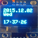
ESP8266 + I2C DS1307 RTC + OLED
ESp8266 で I2C DS1307 RTC を動かしてみました 2015.12.02
Tiny RTC I2C module への電源、SDA, SCL は、3.3V で動作しています。

準備:
RTC Library:Adafruit に感謝。
RTClib.cpp を変更:8行目を除く、4行目から13行目までを削除。
#include <Wire.h>
#include "RTClib.h"
//#ifdef __AVR__
//#include <avr/pgmspace.h>
#define WIRE Wire
//#else
// #define PROGMEM
// #define pgm_read_byte(addr) (*(const unsigned char *)(addr))
// #define WIRE Wire1
//#endif
部品:ESP8266 / I2C OLED / Battery = CR2032 /
部品:I2C DS1307:ebay価格:1個 100円
日時の設定:スケッチ:日時の設定を参照の事。
配線:(例) 電源、接続抵抗を除き、I2C 2本の配線のみです。
_ ESP8266 pin 0 — DS1307 SDA、OLED SDA
_ ESP8266 pin 2 — DS1307 SCL、 OLED SCL
日時の設定:スケッチ:「日時の設定」を参照の事。
_ PCの時刻を設定します。:rtc.adjust(DateTime(__DATE__, __TIME__));
_ UTC(JST)で設定する方法:rtc.begin(); で初期化し、rtc.adjust(DateTime(JST)); で設定。
_ NTPで設定する方法:DS1307 RTC を ESP8266 + UTC(JST)で初期化する
メモ:
秋月通商の DS1307 I2C RTC (1個750円) は、試していません。
DS1307のライブラリーは、幾つかありますが ESP8266 では動かないものがあります。
DS1307は5V仕様だと思うが3.3Vで動いている。
DS3231 という I2C RTC は、電源が 3.3-5.5Vで動作する。ebayで1個202円。
スケッチ:日時の設定。( PCの時刻を設定する方法 ) ( NTPによる方法はこちら )
// DS1307 TIME SET
#include <Wire.h>
#include <RTClib.h>
RTC_DS1307 rtc;

void setup(void) {
  Serail.begin(115200);
  Wire.begin(0,2);                          // Initialisiere I2C
  rtc.begin();
  rtc.adjust(DateTime(__DATE__, __TIME__)); // PCの時刻を設定する。
}

void loop(){
  DateTime now = rtc.now();
  Serial.print  (now.year(),  DEC);Serial.print(".");
  Serial.print  (now.month(), DEC);Serial.print(".");
  Serial.print  (now.day(),   DEC);Serial.print(" ");
  Serial.print  (now.hour(),  DEC);Serial.print(":");
  Serial.print  (now.minute(),DEC);Serial.print(":");
  Serial.println(now.second(),DEC);
  delay(1000);
}
スケッチ:日時の表示
// ESP8266 + DS1307 + OLED                       // 2015.12.02
#include <Wire.h>
#define DS1307_ADDRESS 0x68                      // DS1307 I2C Address
#include <RTClib.h>                              // RTC Module
RTC_DS1307 rtc;                                  // RTC Module
#include <Adafruit_GFX.h>                        // OLED
#include <ESP_Adafruit_SSD1306.h>                // OLED
#define OLED_RESET 4                             // OLED
Adafruit_SSD1306 display(OLED_RESET);            // OLED
char* y[]={"Sun","Mon","Tru","Wed","Thu","fri","Sat"};

void setup() {
  //Serial.begin(115200);
  Wire.begin(0, 2); delay(10);                   // I2C : SDA,SCL
  display.begin(SSD1306_SWITCHCAPVCC,0x78>>1);   // OLED:I2C_ADDRESS
  display.clearDisplay();                        // all pixels off
  display.setTextSize(2);                        // printable sizes 1 to 8
  display.setTextColor(WHITE);                   // WHITE, BLACK, INVERSE
}

void loop() {
  DateTime now=rtc.now();                        // Current time geting from RTC
  display.clearDisplay(); display.setCursor(0,0);// Display Clear,loc 0,0
  //---------------------------------------------// yyyy.mm.dd 2015.12.02
  display.print(now.year());  display.print(".");// year display
  if(now.month()<10){         display.print(0);} // mon  add 0
  display.print(now.month()); display.print(".");// mon  display
  if(now.day()  <10){         display.print(0);} // day  add 0
  display.print(now.day());                      // day  display
  //---------------------------------------------// Week Wed
  uint8_t w = now.dayOfWeek();                   // Weak Read
  String Week = y[w];                            // Week
  display.println(Week);display.println();       // Week
  //---------------------------------------------// Time 12:34:56
  if(now.hour()  <10){        display.print(0);} // hour add 0
  display.print(now.hour());  display.print(":");// hour display
  if(now.minute()<10){        display.print(0);} // min  add 0
  display.print(now.minute());display.print(":");// min  display
  display.print(":");                            // :
  if(now.second()<10){        display.print(0);} // sec  add 0
  display.println(now.second());                 // sec  display
  display.display();                             //
  //---------------------------------------------//
  delay(1000);                                   // 1 sec
}
参考:
DS1307 64 x 8、シリアル、I2Cリアルタイムクロック:
DS1307 data sheet:
Time Library:
Tiny RTC:
JUNKHACK:Tiny RTC DS1307 I2C
JUNKHACK:Tiny RTC DS1307 I2C その2
